Build Your Own Greenhouse the Easy Way
How to Build a Cheap Greenhouse Using a Technique Developed by the U.S. Forest Service

Reading Time: 12 minutes
By Benjamin Hoffman – Have you ever wanted to build your own greenhouse? I was interested in learning how to build a greenhouse to do some raised bed gardening on my homestead. Back in the 1960s, the U.S. Forest Service developed a plan for laminated wooden arches for low-cost housing, using low-cost construction techniques. Thirty years later, faced with the need for a greenhouse and with few resources to build one, I successfully tried the Forest Service idea. This article will describe construction of a jig to make the arches (Fig. 1) and the steps in assembling and erecting them. Use these plans to build your own greenhouse for extending the growing season where you live. You can work toward self-sufficient farm living by learning how to build your own greenhouse.
The Forest Service arches used 1 x 2 top and bottom chords separated by 2 x 6 spacers, but this did not work well with our sharper curvature. Further, I was in the Copper Basin of Alaska, home of the strongest, lightest, knottiest spruce with no chance of a suitable 1 x 2. So we ripped spruce 2 x 4s into 1/2-inch strips (laminae) and laminated two pieces to form a 1″ x 2″ chord. We built several 20′ x 60′ structures including portable versions for flower sales in nearby communities. Five or six people could assemble the frame and cover it with plastic in about two hours, and a dozen people could easily pick it up and move it. The arches were strong, durable and easy to repair; when a car hit an arch and broke it we simply splinted the break.
Back in Maine, after reading Elliot Coleman’s book on winter gardening, I decided to build a 16′ x 18′ winter greenhouse. If you want to build your own greenhouse following these plans, I’ve included step by step illustrations and instructions for you here.
Keep in mind how much winter precipitation your area receives when you want to build your own greenhouse. A 6′ arch spacing was fine in Alaska and has been okay with Maine’s heavier, wet snow loads. For ease of erection, I make a left and right clamshell (Fig. 1), each of two arch sections joined top (ridge), bottom (base) and middle with 1″ x 6″ lumber. Two clams make a basic section 16 feet wide, six feet long, and about 10 feet tall; two men with a stepladder can easily erect it. Two such sections, spaced six feet apart, make an 18-foot long structure that is easily covered with a 20-foot wide roll of poly.
In Alaska we sawed 2 x 4s into 5/8-inch strips with a table saw, a lengthy, frustrating process, then planed them smooth for gluing. In Maine, my neighbor cut four laminae at a time on his Wood-Mizer bandsaw mill in about 1/8 the time to saw them on a table saw, and the band saw cut was smooth enough that planning was not necessary. You’ll have to make appropriate adjustments similar to this when you build your own greenhouse. Saw the laminae before starting the jig, as you need one to shape the arch curve and will also need accurate thickness measurements to make the jig. For my 16 x 18 structure with four arches, I needed 32 laminae, plus a dozen extra to allow for breakage and for other uses. Use 14-foot dimension lumber, either 2 x 6 or 2 x 8, and select it carefully, picking pieces with the fewest and smallest knots. I chose spruce for its high strength and light-weight but yellow poplar would be an excellent choice, if available.
Using a portable band mill, clamp four two-bys on the saw bed and cut four laminae at a time. The leftover 2 x 2s from when you build your own greenhouse this way make great tomato stakes for those indeterminate climbers. Half-inch laminae are fine for greenhouses covered with 6-mil plastic, but 5/8 is better for heavier roofing. To get good glue contact, use planed lumber for spacers.
Build Your Own Greenhouse: Constructing a Jig
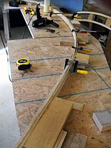
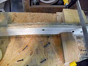
Since a single arch uses two half sections, I built a jig on which to construct a half. First I drew a cross-section of my greenhouse arch on paper, then drew a baseline connecting the top center with the base. I scaled the length of the baseline and at three points—1/4, 1/2 and 3/4 of its length—the distance from the baseline to the curve of the arch. The baseline was less than 12 feet, so my jig table took one piece of oriented strand board (OSB) cut into three pieces and screwed to 2 x 4 supports resting on sawhorses. (Fig. 2)
Diagram 1 (see below) shows the layout of the jig table. Once the OSB was cut and secured to the braces, I transferred measurements of the top, bottom and three midway points (A-E) of the chord from my drawing to the table. At each of these points, I placed a husky wood screw, fitted a lamina inside A and E, and outside B, C, and D, and marked the inside curve of the arch with a pencil. Once the table is completed and the curve marked, Diagram 2 (page 57) will walk you through locating the jig stops.
Build Your Own Greenhouse: Assembling an Arch Section
Once the jig is assembled, it’s time to try the first arch section. The first may take an hour to make, but practice will get it down to 40 minutes. For glue, I have used both waterproof and ordinary yellow carpenter’s glue (Elmer Titebond), with good results from both. Arches made with Titebond II lay exposed in the woods for seven years and have been used for a tractor shed for six years without delaminating. I applied glue with a 1-1/2″ paintbrush.
Trying to bend and fit two glued lamina into place takes several clamps and can be frustrating when you build your own greenhouse this way. To hold the ends of the lower chord in place, cut two dummy spacers equal to the width of a spacer block plus two laminae; place them between the lower chord and the outer stops at A and E to hold the chord in place while installing spacers and gluing the top chord. Most failures in these arches occurred when spacers split along the grain, so use one 3-1/2″ galvanized screw through both top and bottom chords into each spacer, plus one two-inch screw. If, during assembly, a lamination appears to be weak—knot, split, crack—it is easily reinforced by splicing with a short piece of 1/2-inch stock glued and screwed in place (Figure 3).
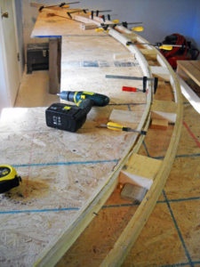
To fit spacers, start at E and work toward A using clamps, as needed, to ensure good glue contact. For small gaps between laminae, sheet-rock screws will draw the pieces together until the glue dries (Fig. 4). For steps 1 through 7, work on the inside of the arch curve, but fit the top chord from the outside of the curve.
MATERIALS (one arch section):
• (4) 1/2 x 2″ by 14′ laminae
• (2) 2 x 4 x 12 end spacers
• (7) 2 x 4 x 4 intermediate spacers
• (22) 3-1/2″ galvanized screws
• (18) 2″ sheet-rock screws
• Jar with yellow carpenter’s glue
• (2) 2 x 4 dummy spacers, length = spacer width + 2 laminae thicknesses
PROCEDURE:
1. Select two laminae for a chord and place the largest defects on the inside (glue) surface to reduce chances of splitting on an outer edge.
2. Apply glue to the inside surfaces of both laminae, place them together, ends even; put a sheet-rock screw about 18″ in from the top end to hold them together for assembly.
3. Fit the two laminae outside the stops B, C, and D and inside stops A and E. At stops A and E pull the chord toward you and slip the dummy spacers between the chord and the stops. The dummies hold proper spacing while you insert spacers and glue the top chord.
4. At each of the seven spacer locations, paint glue on a spacer and the bottom chord where it fits, and position the spacer on the bottom chord, against the spacer stops. Next, insert a 2″ sheetrock screw through the chord about an inch from the left edge of the spacer. Then pre-drill and insert a 3-1/2″ galvanized screw about 1” from the right edge of the spacer.
5. Repeat steps 1 and 2 to prepare the outer chord.
6. Apply glue to both edges of the 12″ spacer at point E and edges of the first three spacers.
7. Remove the dummy spacer at E and insert the 12″ spacer with its bottom, right corner even with the edge of the table. Fit the top chord between the spacer and the outside stop and inside the first two or three outside stops. Pre-drill and insert one 3-1/2″ galvanized screw in each side of the 12″ spacer.
8. Work your way around the top of the chord, one spacer at a time. As you fit the chord inside the stops, paint some glue on the spacer and on the chord where it will touch the spacer. Once the chord is in place, insert a 2″ screw an inch in from the left end of the spacer, then pre-drill and install a 3-1/2″ screw an inch from the right.
9. At the bottom end (A) repeat step 7 as needed to fit the 12″ spacer, then add a 2″ and 3-1/2″ screw into each side of the 12″ spacers at A and E.
10. Trim the chords flush with the bottom end at A. The top will be trimmed later.
11. Pry the arch free of the risers and leave it in the jig for an hour for glue to dry (Fig.5)
Before removing the arch from the jig, trim the ridge end at E as follows. On the 12″ spacer, measure in 3/4″ from its bottom right end and, with a straight edge, draw a line through this point and the upper right corner of the spacer. Extend this line across both top and bottom chords to mark the trim line for the ridgepole and trim the end with a saw.
Because of the moisture in a greenhouse, I recommend painting arch sections with a product such as Thompson’s Water Seal.
Build Your Own Greenhouse: Erecting the Greenhouse
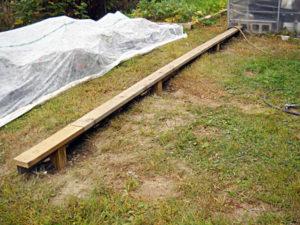
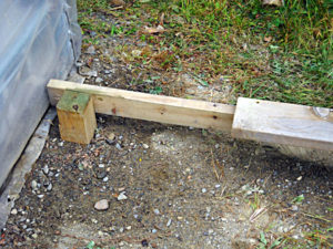
When you build your own greenhouse, erecting the greenhouse takes a minimum of two people and a step-ladder. The more hands, the easier the work, particularly to handle the six-foot clamshells. Also, have some 8-to-10-foot 1 x 4s to use as props to hold clams in place during assembly. I have built similar greenhouses on level ground with no foundation other than some 6′ x 6′ timbers, but recommend the L-girder foundation when you build your own greenhouse. The L-girder foundation can be extended so the greenhouse can be easily moved. With a moveable greenhouse, you can start plants early and slide the greenhouse off after the plants are started, exposing them to the summer sun, wind and rain (saves watering). Another crop can be started in its new location and the house can be moved back to extend the fall season or to start a new, fall/winter crop.
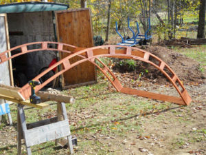
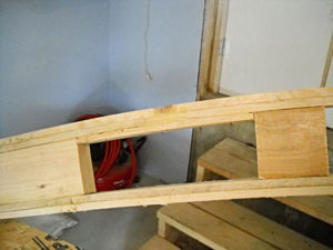
Once the arches are completed (and painted with a moisture resistant finish) make four clamshells like the one in Figure 6. Each clamshell consists of two arches joined at ridge (top), base (bottom) and middle with 1′ x 6′ lumber. The middle (purlin) is notched to fit between the chords and is screwed into the center block. Figure 1 shows left and right clamshells erected on the foundation. Note that the base and middle purlin are the same length (six feet), but the ridge board protrudes (four feet) from the face of the right-hand arch; the ridge of the left-hand section protrudes two feet. The clamshell on the ground at left has a ridge 10 feet long, and when raised, its 10-foot ridge butts against the end of the left clam’s eight-foot ridge (total ridge length is 18 feet). When the third clam is erected, support its left end with a long 1 x 4, clamp the ridge in place and screw the ridge boards together. When the fourth clam (eight-foot ridge) is erected, its ridge butts against the 10-feet of the first clam. Work along the full length of the ridge, leveling and securing it with 1-1/2-inch screws.
It takes at least two people (more is better) with a stepladder (preferably an eight-footer, not a six-footer like mine) to erect the clamshells. When you have erected two, six-foot sections of a one-foot frame, the ridge is 18 feet long, but ensure that the total length of the base is 18 feet. Use 2-1/2-inch screws to secure the bases to the foundation. Once the framework is erected, you are ready to put on the cover, when the wind is calm.
My cover used part of a 100-foot roll of builder’s 6-mil poly (not UV stabilized, not recommended). Unrolled it and cut off 28 feet and, with one helper on each side, got the poly over the structure. First, we pushed most of the roll over the middle purlin. Then, working inside the frame, with a 2 x 4 with three-foot-long board, I lifted the plastic over the ridge and then over the middle purlin on the other side. With one person on each side and one on a ladder under the ridge, we unfolded the plastic toward one end, then the other. To hold the plastic (and strengthen the structure), secure it to the end arches with a single lamina, which will hold it even under severe winds.
Using the ladder, while two helpers held the poly tight, I placed a lamina over the poly on one end arch section, securing it with sheet-rock screws through the top chord, into the spacers. I worked from base to ridge, evening it as I went, and when one side was finished, began at the base of the other and worked back to the ridge. When one end was secured, we went to the other, stretched the plastic and repeated the procedure. Then, to seal the bottom sides, we laid laminae, over the plastic and screwed them into the top plate of the foundation (L-girder). Previously, to put plastic over a frame, I unfolded it first, then tried to get it over the ridge; doing this is much easier. Finishing the end is up to you. Place doors and vents as you think necessary. For framing, I used 2 x 2 pieces left after sawing the lamina on the Wood-Mizer and used scraps of laminae screwed into the spacers to hold plastic in place on the ends.
MATERIALS
(10) 1″ x 6″ bases and purlins, 6’ long*
(2) 1″ x 6″ ridges, 8′ long
(2) 1″ x 6″ ridges, 10′ long
(4) 14′ laminae
(+/-50) 2-1/2″ coated wood screws
(+/-80) 1-1/2″ sheetrock screws, preferably coated
*Note: In snow country, I recommend purlins above the bottom (12″) stops and the first 4″ stops. As heavy snows slide off the plastic, they pack and put tremendous pressure on the bottom few feet of plastic. These purlins can be removed to reduce shade, if necessary, during the growing season.
____________________________________________________

Build Your Own Greenhouse: Diagram 1
Jig Table Construction
MATERIALS:
(1) 4′ x 8′ x 1/2″ sheet of OSB
(1) 2″ x 4″ x 8′ brace
(1) 2″ x 4″ x 12′ brace
(20) 1-1/2″ sheet rock screws
(5) 2″ sheet rock screws
(1) 1/2″ x 2″ x 14′ lamina
PROCEDURE:
1. Cut the OSB into three pieces per diagram.
2. Place the 2″ x 4″ braces on two sawhorses, position the OSB sections and screw the OSB to the braces with 1-1/2″ sheet rock screws.
3. Mark points A–E and drive a 2″ screw into the jig surface to just penetrate the OSB. At A and E, set the screws in from the table edge.
4. Fit one lamina inside points A and E and outside B, C, and D to locate the inner edge of the chord and mark this with a pencil.
____________________________________________________

Build Your Own Greenhouse: Diagram 2
Jig Assembly
MATERIALS:
(3) 2″ x 2″ x 4″ inside stops (B, C, D)
(4) 2″ x 4″ x 4: outside stops
(7) 1″ x 2″ x 4″ spacer stops (assure uniform spacing)
(11) 1″ x 8″ x 1/4″ risers (keep arch from sticking to jig when gluing)
PROCEDURE:
1. From Point A measure 12″ along the arch curve and make a dark pencil mark. Continue along the curve making a mark every 16″ for seven spaces. From E, measure left 12″ and mark the curve.
2. At each mark use a square to erect a perpendicular to the curve and draw a dark line.
3. To the right of the mark at E, glue a 1 x 8 x 1/4 riser (also glue risers perpendicular to the curve at A and E). At all other marks, glue a riser to the left side of the line.
4. At each of the seven middle risers glue a 1 x 2 x 4 stop 2″ above the arch curve (to assure uniform positioning of spacers).
5. At B, C, and D, glue 2 x 2 x 4 inside stops as shown, perpendicular to the curve; secure each with two sheet rock screws from the underside of the table.
6. At the four points shown on the diagram, glue outside stops at distance (width of a spacer plus four laminae) from the curve. Positions of outside stops must allow room for a spacer plus four laminae. Secure each stop from the underside with two screws.
What was your experience when you decided to build your own greenhouse?
Originally published in May/June 2010 issue of Countryside & Small Stock Journal and regularly vetted for accuracy.


Thanks for the details of the arched jig. Are these actual plans from the US Forest Service? Thanks again.
I have been building these for years . A few things I have learned .the chord length will deflect a maximum of 1/6 of itself. That is a 12 foot length will support an arch that is 2 feet deep,soaking the material in water or hot water aids in its flexibility. Wet wood can be glued with urethane construction adhesive, it sets with water. Rather than pulling a curve onto horizontally placed blocks, it uses less material and is more efficient to push the form down into risers that form the curve. I fix my blocks onto the top chord glue and air staples then push it down into the vertical risers tacking here and there with screws,no clamping necessary, then apply glue to blocks and push the inner chord down onto that assembling the truss with air construction staples. Undoing the tack screws it pops from the jig . You can expect 10 % spring back. I layout the curve as a catenary arch. This I found is the simplest tech , I could never understand the massive area and sport to construct horizontal platforms and blocking and clamps etc. A vertical form requires no platforming and can be as simple as hammering stakes in the ground.. for planning select three points one midpoint offset by 1/6 and drape a chain connecting the three, the curve formed is the layout of a catenary arch . Plan using scale grid paper transfer the measure and angles to stakes ,vertical risers, miter the tops and the form is ready to press your trusses.
I have been building these for years . A few things I have learned .the chord length will deflect a maximum of 1/6 of itself. That is a 12 foot length will support an arch that is 2 feet deep,soaking the material in water or hot water aids in its flexibility. Wet wood can be glued with urethane construction adhesive, it sets with water. Rather than pulling a curve onto horizontally placed blocks, it uses less material and is more efficient to push the form down into risers that form the curve. I fix my blocks onto the top chord glue and air staples then push it down into the vertical risers tacking here and there with screws,no clamping necessary, then apply glue to blocks and push the inner chord down onto that assembling the truss with air construction staples. Undoing the tack screws it pops from the jig . You can expect 10 % spring back. I layout the curve as a catenary arch. This I found is the simplest tech , I could never understand the massive area and sport to construct horizontal platforms and blocking and clamps etc. A vertical form requires no platforming and can be as simple as hammering stakes in the ground.. for planning select three points one midpoint offset by 1/6 and drape a chain connecting the three, the curve formed is the layout of a catenary arch . Plan using scale grid paper transfer the measure and angles to stakes ,vertical risers, miter the tops and the form is ready to press your trusses.